Introduction — Why Waterproof Portable Power Is Harder Than It Looks
Most product briefs treat waterproofing as a finishing step: add a rubber gasket, cover the ports, print an IP67 mark on the housing, and move on to the next line item.
Field failures rarely agree with that sequence. Water almost never defeats a product through the surface the team imagined. It enters through a port cavity that was never drained, a button membrane that fatigue-cracked after one season, a screw boss that relaxed after thermal cycling, or a seam that measured perfectly on day one and warped by month six.
Outdoor portable power makes the problem harder because the product is four things at once: a battery system, a power converter, a user interface and a sealed container. Each role pulls the enclosure in a different direction. Ports want openings. Sealing wants fewer openings. Batteries want to shed heat. Waterproofing wants to trap it.
This guide is written for OEM buyers, ODM product teams, product managers and hardware engineers who need to specify, evaluate or develop waterproof portable power. It covers what IP67 actually certifies, where water gets in, how sealing interacts with thermal design, why condensation defeats products that pass immersion testing, and what a defensible validation programme looks like. For wider market and application context, start with our overview of outdoor portable power in 2026.
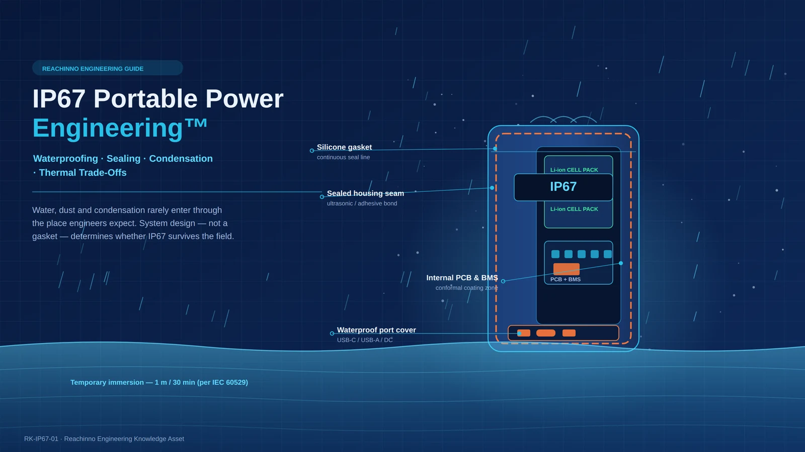
IP67 portable power engineering is not achieved simply by adding rubber seals around a power bank. A reliable waterproof portable power system requires coordinated engineering across the enclosure, sealing, ports, buttons, gaskets, pressure management, condensation control, thermal management, battery protection, mechanical durability and environmental validation. Waterproofing and thermal management can also conflict: a completely sealed enclosure improves ingress protection while making heat dissipation and internal moisture management more difficult. That is why IP67 should be treated as a system-engineering requirement across the whole product, not as a single certification target to be met at the end of development.
Table of Contents
- What Does IP67 Actually Mean?
- Why IP67 Does Not Automatically Mean Outdoor Reliability
- The Five Critical Water Entry Points in Portable Power
- Reachinno Waterproofing Architecture™
- Sealing Methods for Portable Power Products
- The Hidden Problem: Condensation Inside a Sealed Power Bank
- Waterproofing vs Thermal Management
- Mechanical Durability Can Destroy Waterproofing
- Ports Are Usually the Weakest Point
- Battery Safety Inside a Waterproof Enclosure
- IP67 Portable Power Validation Matrix
- Laboratory IP Testing vs Real Outdoor Use
- IP67 Portable Power OEM Decision Matrix
- Five Common Waterproof Portable Power Design Mistakes
- What OEM Buyers Should Specify
Part 1 — What Does IP67 Actually Mean?
IP stands for Ingress Protection. The two-digit code is defined by IEC 60529, which describes test methods and classifications for enclosures of electrical equipment. The code is deliberately narrow: it tells you how a sample behaved under a specific laboratory procedure, and nothing more.
- First digit — solids and dust. A rating of 6 means dust-tight: no ingress of dust under the defined test conditions. It is the highest solids classification in the standard.
- Second digit — water. A rating of 7 means protection against the effects of temporary immersion in water under defined conditions of pressure and time.
Those definitions matter because buyers routinely read more into them than the standard supports. IP67 does not mean waterproof forever, ocean-proof, saltwater-proof, impact-proof, UV-proof or condensation-proof. It does not cover pressurised jets, hot water, steam, chemicals or long-duration submersion. It says nothing about how the product will behave after a year of UV exposure, two hundred charge cycles and a drop onto gravel.
Practical implications for portable power:
- The test is performed on new samples in clean, still water, within a defined temperature differential between water and sample.
- The test does not cycle the product through heat, cold, UV or mechanical wear beforehand.
- Passing IP67 does not require the enclosure to remain dry inside; condensation formed during or after the test is outside the scope of the classification.
- Certification is typically performed on a representative sample, not on every production unit. Process control is what protects the rest of the batch.
Part 2 — Why IP67 Does Not Automatically Mean Outdoor Reliability
Outdoor deployment stacks loads that IP testing never applies. Sunlight, salt air, mud, vibration, repeated port use and daily temperature swings act on the same sealing system at the same time. A rating that answers one question well does not answer the others.
| Requirement | Covered by IP67? | Additional Engineering Needed? |
|---|---|---|
| Dust and fine particulate | Yes — first digit 6 | Sealed connectors, abrasion-resistant finishes, wipe-clean surfaces |
| Temporary immersion in clean water | Yes — second digit 7 | Drainage paths, drying guidance, post-immersion inspection |
| UV exposure | No | UV-stable polymers and elastomers, coatings, accelerated UV validation |
| Salt spray and coastal exposure | No | Corrosion-resistant fasteners and contacts, salt spray validation |
| Condensation | No | Assembly humidity control, coating strategy, membrane and pressure design |
| Drop impact | No | Reinforced structure, energy-absorbing features, drop testing on aged units |
| Thermal cycling | No | Gasket compression retention, cycling validation across the operating range |
| Solar exposure | No | Thermal path design, solar-load testing, high-temperature derating |
| Connector corrosion | No | Plating selection, sealed receptacles, contact lubrication strategy |
| Long-term outdoor deployment | No | Combined-environment and real field trials over months, not hours |
The takeaway for sourcing teams: an IP rating is one layer of environmental reliability, not the whole structure. Market demand for rugged outdoor products has grown steadily, and the engineering detail behind that demand is covered in the 2026 Power Bank Industry Report.
Part 3 — The Five Critical Water Entry Points in Portable Power
Every waterproof portable power product has the same set of weak interfaces. Water only needs one of them to fail. Treating these five points as a checklist — early, before the enclosure is frozen — prevents most of the failures seen in the field.
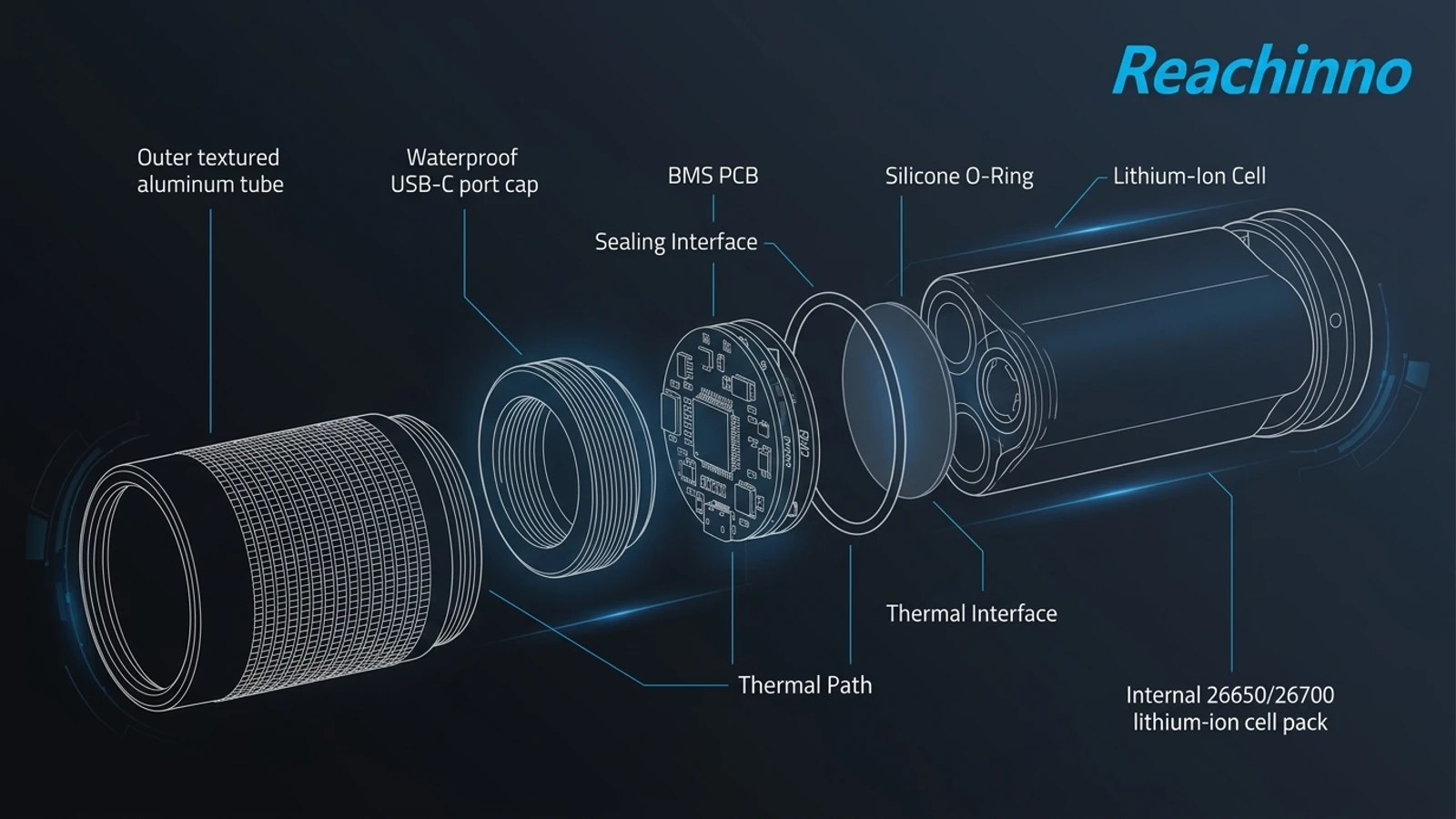
1. USB and DC Ports
Failure mechanism. A port is an open cavity by design. Water enters by capillary action, by splash, or by migration along a wet cable left plugged in. If the cavity has no drainage path, water sits against the connector and eventually reaches the PCB through pin gaps or the connector’s own body.
Engineering solution. Use a sealed receptacle where the connector itself carries an ingress rating, add a silicone plug or hinged cover, and give the cavity a drainage and drying path so residual water can leave rather than pool.
Trade-off. Covers add user friction and are easy to forget or lose; sealed receptacles and internal potting add cost, thickness and assembly steps.
Manufacturing risk. Missed cover installation, insufficient cover compression, torn tethers, and connector skew that opens a gap on one side of the bezel.
2. Buttons and Switches
Failure mechanism. A moving part breaks the continuous seal line. Key membranes flex thousands of times; fatigue cracking or excessive travel eventually opens a path. Water that reaches the switch then travels along the actuator into the cavity.
Engineering solution. Integrate the key into the sealing layer using a silicone membrane or an overmolded key, limit travel mechanically, and isolate the switch area from the main electronics cavity where possible.
Trade-off. Tactile feel gets firmer, travel gets shorter, and tooling cost rises compared with a separate button plus gasket.
Manufacturing risk. Poor adhesion at the overmold interface, uneven membrane wall thickness, and keys that stick or double-trigger after tolerance stack-up.
3. Housing Seams
Failure mechanism. Seams fail from uneven compression rather than from a bad gasket. Shell warpage, thin walls, insufficient screw density and thermal cycling all reduce contact pressure along part of the seam — and water finds the low-pressure section.
Engineering solution. Increase shell stiffness with ribs and adequate wall thickness, keep screw pitch tight near corners, and consider ultrasonic welding or structural adhesive bonding to convert the seam into a continuous joint.
Trade-off. Welded or bonded seams are effectively non-serviceable, and stiffening features add weight and mould complexity.
Manufacturing risk. Narrow welding energy window, adhesive cure time and surface-preparation sensitivity, and shell flatness drifting outside tolerance at high cavity counts.
4. Screws and Mechanical Interfaces
Failure mechanism. A threaded hole is a ready-made channel. If the boss opens into the internal cavity, water follows the thread. Vibration and thermal cycling then reduce torque over time, which relaxes the very compression the gasket depends on.
Engineering solution. Use blind bosses that do not break into the cavity, seal under the screw head with an O-ring or bonded washer, control assembly torque, and add thread-locking or anti-loosening features where vibration is expected.
Trade-off. More parts, more assembly steps and a defined torque process that must be audited on the line.
Manufacturing risk. Torque decay after thermal cycling, adhesive wicking onto the sealing face, and blind-boss depth too shallow to hold the specified engagement.
5. Cable and Connector Entry Points
Failure mechanism. Strain applied to a cable transfers directly into the sealing structure. Repeated pull loosens the gland, and the gap between cable jacket and strain relief becomes a capillary path.
Engineering solution. Provide genuine strain relief with adequate clamp length, use overmolded cable assemblies, and secure the cable internally so external load never reaches the seal.
Trade-off. Larger overall volume, and cables that become custom parts instead of commodity ones.
Manufacturing risk. Strain-relief length shorter than the design intent, weak bond between overmold and jacket, and internal clamps skipped during rework.
Part 4 — Waterproofing Architecture: A System, Not a Gasket
Waterproofing decisions interact. A stiffer enclosure reduces gasket compression loss. A better port design reduces the burden on the housing seal. A validation plan built around real exposure catches the combinations that component-level thinking misses. The Reachinno Waterproofing Architecture™ below describes that sequence.
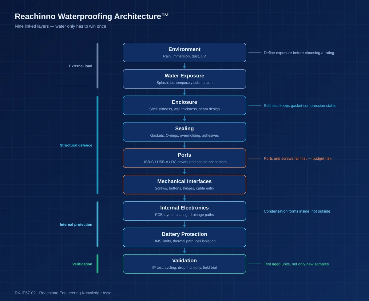
- Environment → Water Exposure. Define the real exposure — rain, splash, jet, mud, temporary immersion, coastal air — before selecting any rating.
- Enclosure → Sealing. Stiffness and seam design determine whether the seal survives; gasket material only determines how well it seals while compressed.
- Ports → Mechanical Interfaces. The two layers where most field leaks originate, and where cost is most often cut first.
- Internal Electronics → Battery Protection. If water or condensation gets past the outer layers, internal protection decides whether the failure is cosmetic or safety-relevant.
- Validation. Verification closes the loop. Without it, every layer above is an assumption.
This layered view is the waterproofing instance of the broader Reachinno Outdoor Energy Ecosystem™, which places environmental validation as a first-class engineering layer rather than a final checkpoint.
Part 5 — Sealing Methods for Portable Power Products
There is no universally best sealing method. Each one trades cost, manufacturability, serviceability and long-term stability against the level of protection it delivers. Selections made here also determine whether the product can be repaired, refurbished or recycled at end of life.
| Method | Advantages | Limitations | Cost impact | Manufacturing complexity | Repairability | Suitability |
|---|---|---|---|---|---|---|
| Silicone gasket | Wide temperature range, good compression recovery, re-usable | Tears easily, needs compression space, relatively high gas permeability | Medium | Medium — groove design and compression control | Good | High — primary housing seal |
| Foam / sponge gasket | Seals at low compression force, fills gaps, light | Compression set over time, water uptake with open-cell types | Low–medium | Low — die-cut and apply | Good | Medium — dust and secondary sealing |
| Overmolding | Seal integrated into the part, no loose component | High tooling cost, depends on material bonding | High | High | Poor | High — keys, cable exits, local seals |
| Double-shot molding | Strongest interface, no assembly variation | Very expensive tooling, limited material pairing, hard to modify | Very high | Very high | Poor | Medium–high — high-volume programmes |
| Ultrasonic welding | No consumables, fast cycle, continuous joint | Thermoplastics only, non-serviceable, narrow process window | Medium | Medium–high | Poor — destructive | High — shell closure |
| Adhesive bonding | Joins dissimilar materials, fine seal lines possible | Cure time, surface-preparation sensitive, ageing and chemical compatibility | Medium | Medium — dispensing accuracy | Poor | Medium–high |
| O-rings | Mature, standardised, handles pressure differential | Needs precision groove, can twist or displace, may need lubrication | Low | Medium — groove machining | Good | Medium — screws, circular interfaces |
| Waterproof connectors | Interface itself carries an ingress rating | Expensive, bulky, limited selection, finite mating life | High | Medium | Medium | High — industrial and external interfaces |
| Port covers | Low cost, replaceable, visible to the user | Easily left open, lost, or worn out | Low | Low | Good | High — essential on consumer products |
A practical note on gasket design: compression is a design parameter, not an assembly accident. Elastomer seals are typically designed to work within a defined compression band across the full tolerance stack, and the material’s compression-set behaviour at the product’s maximum operating temperature is what determines whether that band still exists after two years. Both need to be specified on the drawing, not left to the moulder.
Part 6 — The Hidden Problem: Condensation Inside a Sealed Power Bank
A product can pass every water ingress test and still ship with a moisture problem. Condensation is generated inside the enclosure, so no external seal can prevent it. This is the single most underestimated failure mode in waterproof portable power.
Water appears inside a sealed product through several routes. Air sealed in at assembly already carries humidity. Daily temperature swings drive pressure changes that pump moist air through microscopic seal paths. Warm internal air meeting a cold shell wall drops below its dew point, and droplets form on the coldest surface — usually the inside of the housing or a metal shield.
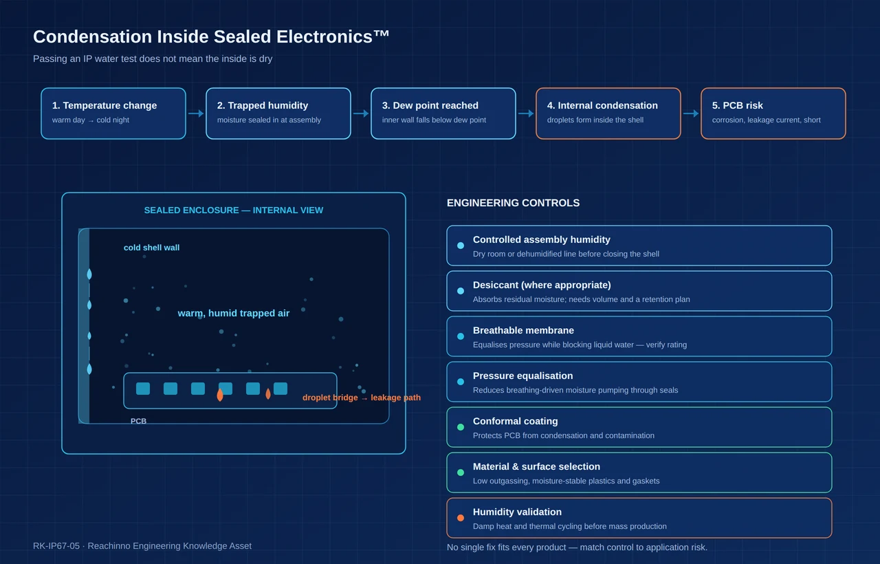
Sealed does not mean dry. Once moisture is inside, a better external seal can actually make the situation worse by removing the paths through which it would otherwise escape.
Engineering approaches, each with conditions attached:
- Controlled assembly environment. Closing the shell in a dehumidified line removes moisture before it is sealed in. Often the highest-return measure and the cheapest.
- Desiccant, where appropriate. Absorbs residual moisture, but needs internal volume, a retention method and a defined service life.
- Breathable membrane solutions, where applicable. Membranes can equalise pressure while blocking liquid water, which reduces the breathing effect that pumps moisture in. The membrane’s own rating and contamination behaviour must be validated for the application.
- Pressure equalisation. Reduces the differential that drives breathing in the first place.
- Material selection. Low-outgassing, moisture-stable polymers and elastomers reduce internal humidity sources.
- PCB protection. Conformal coating, where appropriate, protects against condensation and contamination rather than preventing either.
- Humidity validation. Damp-heat and thermal cycling expose the problem before customers do.
Temperature swings are largest when a cold product is carried into warm, humid air — the same mechanism that makes portable power systems working in extreme cold vulnerable to internal moisture. See our guide to -40°C portable power engineering for the cold-side of this problem.
No single solution fits every product. A small consumer unit with a short duty cycle has a different moisture budget from a fixed industrial device expected to sit outdoors for five years.
Part 7 — Waterproofing vs Thermal Management
Waterproofing and thermal management pursue opposite goals. Sealing removes openings; cooling needs paths. Once the enclosure is closed, heat can leave only by conduction through the shell and by radiation — both far less effective than the convection a vented design gets for free.
The chain is simple and unforgiving: more sealing leads to less airflow, which leads to greater heat accumulation, which raises internal component temperature, which accelerates battery ageing and triggers earlier thermal derating. The result is a product that survives the rain and disappoints on runtime.
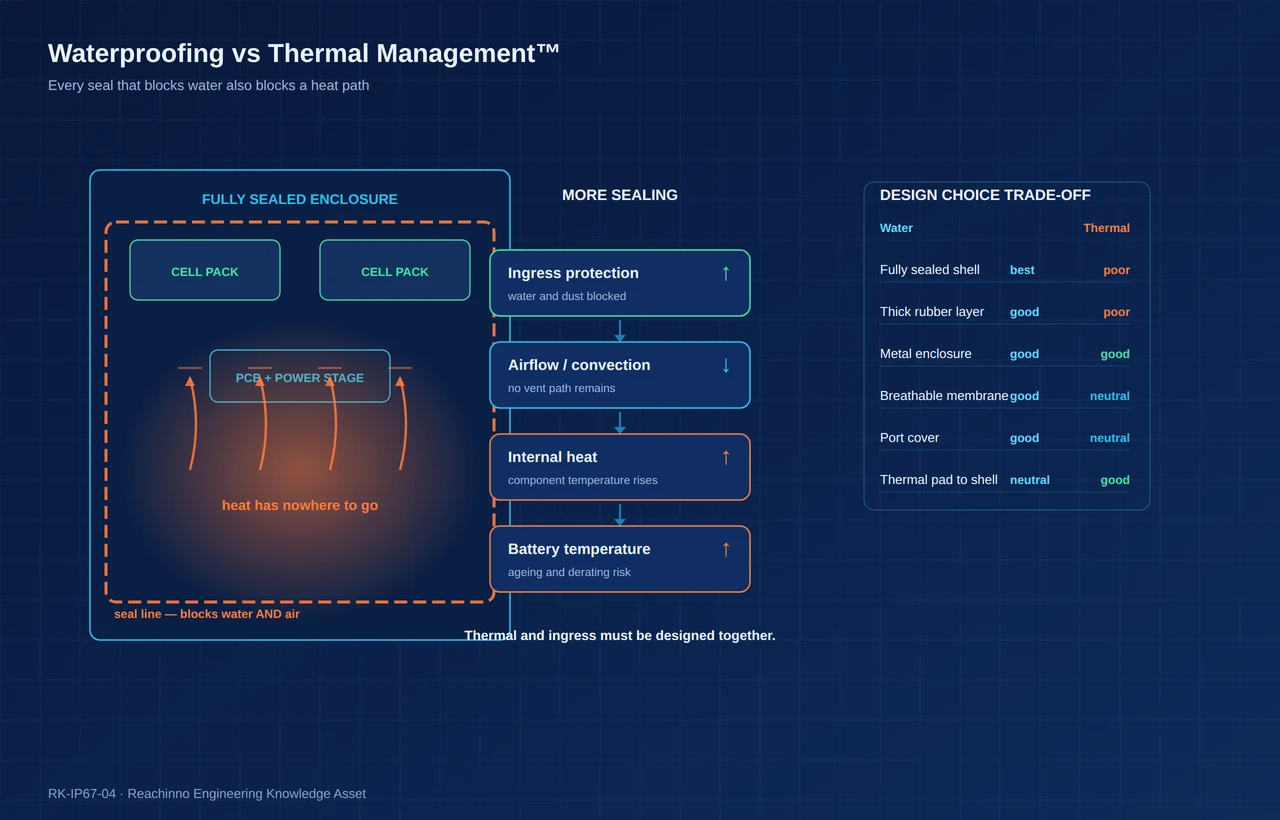
| Design Choice | Waterproof Benefit | Thermal Trade-Off |
|---|---|---|
| Fully sealed enclosure | Highest protection; no direct path for water or dust | No convective path; heat leaves only through the shell, raising internal temperature |
| Thick rubber layer | Absorbs impact and improves seal compliance | Rubber has low thermal conductivity and becomes an insulating blanket |
| Metal enclosure | High stiffness keeps compression stable over time | Conducts heat outward well, but heats quickly under sun load and raises surface temperature |
| Waterproof membrane | Equalises pressure while blocking liquid water | Does not improve heat transfer; addresses moisture rather than temperature |
| Port cover | Protects the weakest opening | Creates a small dead volume where local heat is slow to dissipate |
| Thermal pad to shell | Neutral — it is an internal measure that does not breach the seal | Moves heat into the shell, lowering internal temperature while raising surface temperature |
Because the two disciplines pull against each other, they have to be designed together from the first architecture review. The interaction is covered in more depth in our guide to high-temperature portable power engineering.
Part 8 — Mechanical Durability Can Destroy Waterproofing
Ingress protection is a property of a product at a point in time. A unit can pass IP67 on the day it is built and fail the same test after a season of real use, because the sealing system degrades mechanically.
- Drop and impact crack shells, shift sub-assemblies and open seams.
- Vibration loosens fasteners and relaxes gasket compression.
- Thermal cycling repeatedly expands and contracts the joint, and accelerates compression set in elastomers.
- UV ageing embrittles external polymers, covers and exposed gasket edges.
- Repeated port and button use wears the very features that do the most sealing work.
This is why environmental reliability cannot be validated without mechanical validation. The sealing system and the structural system are the same system. Our mechanical design for portable power framework covers how structure, fastening and enclosure stiffness are specified before sealing is designed around them.
Part 9 — Ports Are Usually the Weakest Point
Ports complicate waterproofing because they must be open to function. USB-C, USB-A and DC barrels are cavities with electrical contacts at the bottom. Magnetic connectors and wireless charging reduce the opening count, which is why they appear in rugged designs — but each brings its own trade-off.
- USB-C is small and now nearly universal, but its cavity is tight, drainage is difficult, and debris plus moisture accelerates contact corrosion.
- USB-A has a larger opening and a looser mechanical fit, which makes sealing harder and debris retention more likely.
- DC barrels are robust mechanically but add another cavity and usually need a separate cover.
- Magnetic connectors remove the cavity from the charging path, but introduce alignment, retention and debris-on-magnet issues.
- Wireless charging removes a port entirely on the input side, though it introduces coil heat inside a sealed enclosure — a thermal problem that must be solved in the same review.
Design decisions that consistently help:
- Port covers are cheap and effective but rely on user behaviour.
- Sealed receptacles move protection into the component, at higher unit cost.
- Internal sealing — a sealed internal cavity behind a drainable outer chamber — keeps water away from electronics even when it enters the port.
- Connector positioning matters: upward-facing ports collect water, downward or side-facing ports with drainage do less so.
- Drainage strategy should be deliberate, with a path out and no place for water to sit.
- Corrosion resistance — plating and contact finish selection — determines what happens after the inevitable small exposure.
- User experience closes the loop: a cover that is annoying to close will eventually stay open.
Part 10 — Battery Safety Inside a Waterproof Enclosure
Waterproofing does not remove battery risks, and in some respects it changes them. A sealed enclosure has to be engineered with the cell’s mechanical, thermal and electrical behaviour in mind.
- Thermal expansion. Cells and potting compounds expand at different rates; internal layout needs room for that movement.
- Gas generation. A cell that vents into a perfectly sealed, rigid enclosure raises internal pressure. Design must consider how that event is handled mechanically.
- Pressure. Even normal operation produces pressure change from temperature swings; the enclosure and any membrane must accommodate it.
- Thermal runaway protection. Sealing does not prevent propagation. Cell spacing, barriers and thermal paths still matter.
- Temperature monitoring. Sensor placement should reflect the sealed thermal reality, not an open-air assumption.
- BMS protection. The BMS remains the gatekeeper for over-temperature, over-current and cell-balancing limits.
- Heat paths. Defined conduction routes from cells to shell are more important when convection is unavailable.
- Emergency failure behaviour. How the enclosure behaves in a worst-case event should be a design input, not an afterthought.
Part 11 — IP67 Portable Power Validation Matrix
Validation is where waterproofing claims become defensible. The matrix below lists the checks that matter for outdoor portable power, what each one is for, and the risk carried by skipping it.
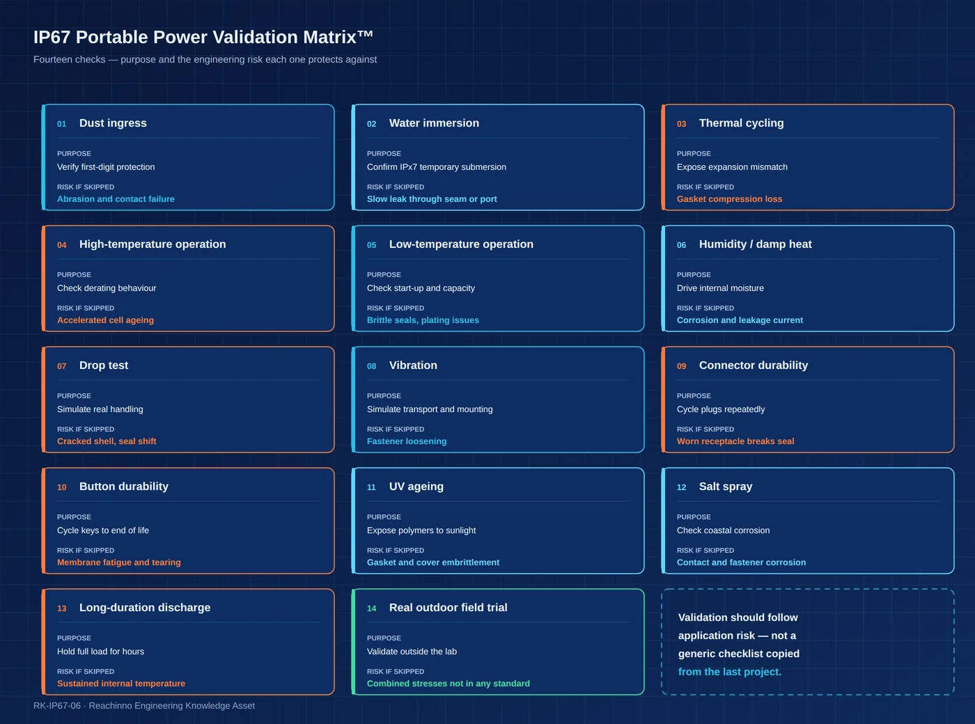
| Test | Purpose | Engineering Risk |
|---|---|---|
| Dust ingress | Verify the first-digit protection under the IEC 60529 procedure | Abrasion, contact failure, blocked vents and covers |
| Water immersion | Confirm IPx7 behaviour for temporary submersion | Slow leak through a seam, port or cover that only appears after minutes |
| Thermal cycling | Expose expansion mismatch between shell, gasket and fasteners | Loss of gasket compression and fastener torque |
| High-temperature operation | Confirm derating behaviour and protection thresholds | Accelerated cell ageing and unexpected power reduction |
| Low-temperature operation | Confirm start-up, capacity and charging limits in cold | Brittle seals, condensation on warm-up, plating issues |
| Humidity / damp heat | Drive internal moisture to expose condensation behaviour | Corrosion, leakage current and latent field failures |
| Drop test | Simulate real handling on representative surfaces | Cracked shell, shifted sub-assembly, opened seam |
| Vibration | Simulate transport, mounting and carried use | Fastener loosening and connector fretting |
| Connector durability | Cycle plugs through the expected service life | Worn receptacle that no longer seals or retains |
| Button durability | Cycle keys to end of life | Membrane fatigue, tearing and loss of tactile feedback |
| UV ageing (where applicable) | Expose polymers and elastomers to sunlight | Embrittled covers, gaskets and external latches |
| Salt spray (where applicable) | Check behaviour in coastal or marine-adjacent air | Corrosion of contacts, fasteners and coatings |
| Long-duration discharge | Hold rated load for hours inside a sealed shell | Sustained internal temperature beyond the design assumption |
| Real outdoor field trial | Validate outside the laboratory | Combined stresses that no single standard reproduces |
Order matters. Testing immersion first and drop last tells you whether a wet product survives handling; reversing the order tells you whether a damaged product resists water. Both sequences are meaningful — the point is to choose them deliberately. An example of how this integrates into a delivered programme is our IP67 rugged power solution.
Part 12 — Laboratory IP Testing vs Real Outdoor Use
Laboratory IP certification tests a defined condition. Real deployment is a sequence of conditions that rarely repeat the lab arrangement.
- Rain arrives wind-driven, at an angle, often mixed with dust.
- Mud and grit abrade covers and sit in cavities.
- UV degrades polymers continuously rather than in a single exposure.
- Heat and cold alternate daily, driving pressure cycling.
- Solar exposure adds a thermal load that no immersion test includes.
- Mechanical use — plugging, unplugging, button presses — accumulates thousands of cycles.
- Condensation forms overnight, independent of any rain event.
Certification is therefore a necessary checkpoint, not proof of complete field reliability. The gap between the two is explored further in our overview of extreme-weather portable power engineering.
Part 13 — IP67 Portable Power OEM Decision Matrix
Different applications carry different risk profiles. A cycling product faces sustained rain and vibration; an agriculture device faces washdown and chemicals; a security installation faces months of continuous exposure with no user intervention. The right protection strategy follows the profile.
| Application | Water Risk | Dust Risk | Impact Risk | Thermal Risk | Recommended Protection Strategy |
|---|---|---|---|---|---|
| Camping | Medium | Medium | Medium | Low–medium | Sealed shell with covered ports, drop validation on aged units |
| Cycling | High | Medium | Medium–high | Low | Enhanced sealing, vibration validation, mount-compatible port location |
| Outdoor lighting | High | Medium | Low | Medium | Weatherable polymers, UV validation, condensation control |
| Security cameras | High | Medium | Low | Medium | Fixed-installation sealing, cable gland, salt spray and UV validation |
| Industrial IoT | Medium–high | High | Medium | Medium | Rated connectors, wide-temperature validation, serviceable sealing |
| Agriculture | Medium–high | High | Medium | Medium | Washdown-ready design, chemical compatibility, sealed cable entry |
| Marine-adjacent | Very high | Medium | Medium | Medium | Corrosion-resistant hardware, salt spray validation, no long-term immersion |
| Emergency equipment | High | Medium | High | Medium | Sealing plus drop and long-storage validation, immediate readiness checks |
| Disaster response | Very high | High | High | Medium–high | Full-environment validation, redundant sealing, supervised field trial |
Part 14 — Five Common Waterproof Portable Power Design Mistakes
Mistake 1 — Treating IP67 as a Cosmetic Feature
A printed rating on the housing does not survive contact with water. If sealing is not backed by geometry, material selection, process control and validation, the mark on the shell is marketing rather than engineering.
Mistake 2 — Designing Waterproofing After the Enclosure Is Finished
Sealing needs compression space, groove geometry, stiffness and screw pitch. When those are decided by an industrial design freeze without sealing input, the gasket becomes a patch rather than a system, and every fix costs more than it would have at concept stage.
Mistake 3 — Ignoring Condensation
Teams validate against water coming in and never test moisture that was sealed in or formed inside. Condensation failures surface months later, when the product has already shipped and the root cause is hard to trace.
Mistake 4 — Ignoring Thermal Trade-Offs
A sealing improvement that raises internal temperature by a meaningful margin can reduce cycle life and usable capacity. Without a co-designed thermal path, the product trades a visible failure for an invisible one.
Mistake 5 — Testing the Product Only When New
Protection degrades. Validation on fresh samples says nothing about behaviour after drops, cycling, UV and thousands of port insertions — which is exactly when customers discover whether the design held up.
Part 15 — What OEM Buyers Should Specify
The weakest waterproofing RFQ is a single line: “need an IP67 power bank.” It cannot be engineered against, quoted accurately or validated, because it does not describe the environment the product has to survive.
A strong engineering RFQ defines:
- Water exposure — rain, splash, jet, temporary immersion, and how often
- Dust exposure — fine dust, sand, mud, and whether cleaning is expected
- Operating temperature — continuous and peak, with duration
- Solar exposure — direct sun, mounting orientation, surface colour
- Humidity — typical range and whether condensation cycles are expected
- Immersion scenario — depth, duration, water type, and whether it repeats
- Port requirements — connector types, count, orientation, cover expectations
- Charging method — wired, magnetic, wireless, solar input
- Output power — continuous and peak, and the duty cycle behind them
- Runtime — at what load, at what ambient temperature
- Drop requirement — height, surface, number of events, and whether the product must still be sealed afterwards
- Expected product lifetime — years in service, and the environment across that period
- Certification markets — which standards and marks apply in the target regions
Written this way, the RFQ becomes a specification a supplier can engineer against and a buyer can validate — rather than a rating that both parties interpret differently.
Conclusion — Design Protection Around the Application
Environmental protection has to be designed around the application, not added after the product is finished. The sequence below is the shortest summary of this guide:
- Application → Environment. Where and how the product is used.
- Environment → Ingress Risk. Which entry points actually matter.
- Ingress Risk → Mechanical Design. Stiffness, seams, fastening and covers.
- Mechanical Design → Thermal Design. Heat paths in a closed enclosure.
- Thermal Design → Electrical Protection. Coating, BMS limits and monitoring.
- Electrical Protection → Validation. Testing the combinations, on aged units, in the field.
IP67 is a useful, well-defined target. Treated as a system requirement, it produces products that survive. Treated as a label, it produces warranty claims.
Related Engineering Resources
Industry Research
Framework
Technical Guides
Engineering Solution
Engineering Case Study
FAQ
The first digit (6) means the enclosure is dust-tight under IEC 60529 test conditions. The second digit (7) means it is protected against the effects of temporary immersion in water under defined conditions of depth and time. It does not describe behaviour after ageing, impact, UV exposure or salt exposure.
In general, an IP67-rated product is designed to tolerate rain and splashing. Two practical cautions apply: port covers must be closed, and the rating reflects the condition of the product as tested. A unit with a damaged cover, a cracked shell or a worn port should not be assumed to still meet its rating.
No. IP testing is performed with clean water and does not cover corrosion. Saltwater and salt-laden air attack contacts, fasteners and coatings through mechanisms the rating does not address. Marine-adjacent applications need corrosion-resistant hardware and salt spray validation in addition to ingress protection.
Yes, if the port is unsealed or the cover is open. A port is an open cavity, and water can enter by splash or by migrating along a wet cable. This is why USB-C is usually the first entry point in a field failure analysis, and why sealed receptacles, covers and drainage paths are treated as primary design items.
No. Condensation forms inside the enclosure when trapped humid air meets a surface below its dew point. Because it is generated internally, no external seal can prevent it. Assembly humidity control, breathable membranes, conformal coating and humidity validation are the measures that address it.
Generally yes. Sealing removes convective airflow, so heat leaves through the shell by conduction and radiation instead. That is why rugged products often need defined thermal paths, thermal pads to the housing, and conservative power derating — and why ingress and thermal design should be reviewed together.
Not necessarily. A drop can crack the shell, shift internal assemblies and relax gasket compression along a seam. Ingress protection is a property measured at a point in time; without mechanical validation on aged or impacted units, the rating should not be assumed to persist after impact.
More than a rating. Define water exposure type and frequency, dust exposure, operating and storage temperature, solar exposure, humidity, immersion scenario, port requirements, charging method, output power and duty cycle, runtime target, drop requirement, expected lifetime and target certification markets. That converts a marketing label into an engineering specification.