Engineering Portable Power for Extreme Heat: Battery Thermal Management, Solar Exposure and High-Temperature Reliability
Extreme-heat portable power is a system-engineering problem, not simply a battery-temperature problem. High ambient temperature, direct solar exposure, charging losses, high output power, enclosure design and internal heat generation can combine to push battery and electronic components beyond their preferred operating range.
A reliable high-temperature portable power system therefore requires coordinated engineering across cell chemistry, battery pack design, BMS, power conversion, thermal paths, enclosure materials, charging strategy, solar exposure and environmental validation.
For OEM products intended for hot outdoor environments, the correct specification is not simply “operate at 50°C.” The engineering team should define ambient temperature, internal component temperature, load profile, charging condition, solar exposure, runtime and acceptable performance degradation.
Introduction: Heat Is a System Problem
Portable power products are increasingly being used outside controlled indoor environments.
Camping, cycling, outdoor lighting, emergency communications, security monitoring, agriculture, remote infrastructure and disaster-response equipment can all expose batteries and electronics to elevated temperatures.
For conventional consumer electronics, temperature management is already an important design consideration. Apple, for example, states that iPhone and iPad devices are designed for use between 0°C and 35°C, and that charging may slow or stop when a device becomes too hot. Apple also warns that prolonged exposure to temperatures above 35°C can permanently reduce battery lifespan (Apple Support). This transition is part of the larger transformation documented in Reachinno’s 2026 Power Bank Industry Report.
Outdoor portable power systems face a more complicated problem.
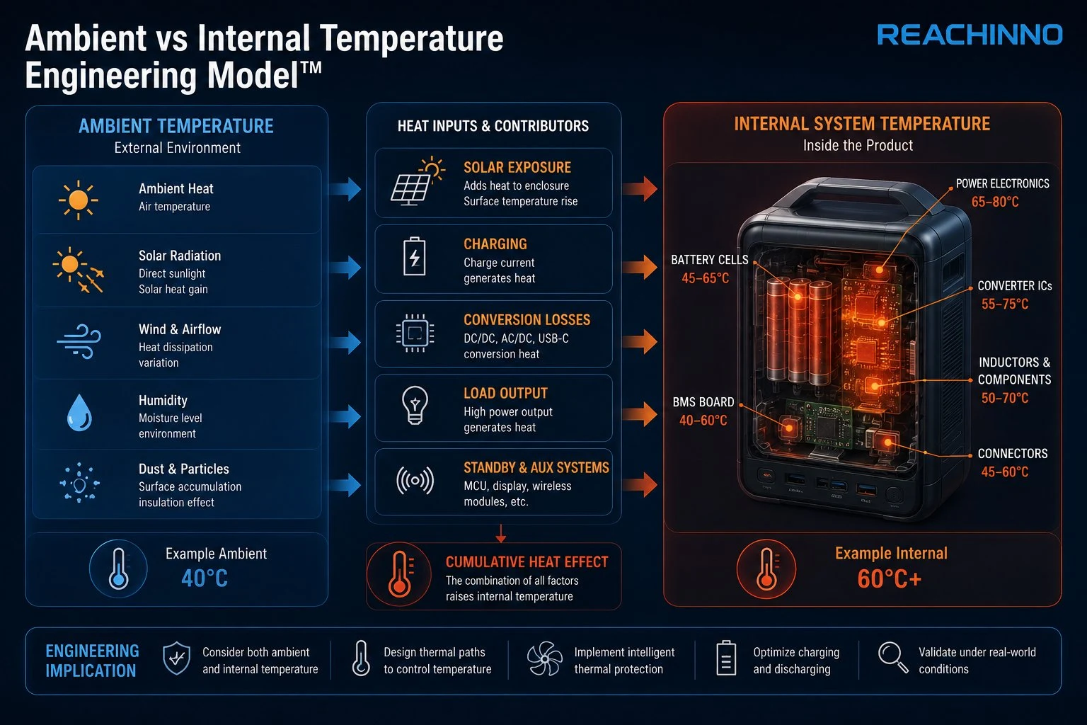
The temperature surrounding the product may be 40°C, while direct sunlight, dark enclosure surfaces, battery charging, DC/DC conversion and high output power can raise the internal temperature substantially higher.
This creates a fundamental engineering question:
How do you keep a portable power system reliable when the environment itself is continuously adding heat?
The answer is not simply to select a “high-temperature battery.”
The entire system must be engineered together.
Environment → Solar Exposure → Battery → BMS → Power Electronics → Thermal Path → Enclosure → Load → Validation
This article explains how OEM and ODM product teams should approach portable power for extreme heat. For the broader environmental engineering framework covering cold, heat, water, solar and emergency scenarios, see our Extreme-Weather Portable Power in 2026 engineering guide.
Part 1 — Why Extreme Heat Changes Portable Power Engineering
1. What Makes High-Temperature Portable Power Different?
A conventional power bank is generally optimized around capacity, output power, charging speed, size, weight and cost.
A high-temperature outdoor product requires a much broader engineering matrix.
| Engineering Factor | Conventional Power Bank | Extreme-Heat Solution |
|---|---|---|
| Battery capacity | Important | Important |
| Energy density | Important | Important |
| Cell chemistry | Important | Critical |
| Internal resistance | Important | Critical |
| Battery temperature | Important | Critical |
| BMS temperature protection | Standard | Application-specific |
| Charging temperature | Important | Critical |
| Thermal management | Moderate | Critical |
| Solar exposure | Often ignored | Critical |
| Enclosure | Cosmetic + structural | Thermal + structural |
| Connector temperature | Secondary | Important |
| Standby power | Important | Critical for long runtime |
| Outdoor validation | Limited | Essential |
This is why adding a rubberized exterior to a standard power bank does not automatically create a reliable hot-weather product.
The enclosure itself can become part of the thermal problem.
2. Ambient Temperature Is Not Battery Temperature
This is one of the most important concepts in outdoor power engineering.
Suppose an outdoor product is deployed at 40°C ambient temperature.
That does not mean battery = 40°C.
The battery may experience solar radiation, internal heat generation, charging heat, discharge heat, converter losses, PCB heat and enclosure heat accumulation.
Therefore:
Ambient temperature is an environmental specification. Component temperature is an engineering specification.
This distinction should be included in the product requirements document.
Part 2 — How Heat Affects Lithium-Ion Batteries
3. Why Does High Temperature Accelerate Battery Aging?
Lithium-ion batteries are electrochemical systems. Their performance depends on reactions occurring at the electrode/electrolyte interfaces.
As temperature rises, many unwanted side reactions become faster. The U.S. Department of Energy notes that degradation mechanisms in lithium-ion batteries are strongly influenced by temperature and state of charge, with undesirable side reactions increasing as temperature rises (DOE — Chapter 4 Technology).
The engineering consequences can include:
- accelerated capacity loss
- increased internal degradation
- electrolyte degradation
- interfacial film growth
- increased gas generation under some conditions
- increased cell imbalance
- shortened cycle life
- reduced long-term reliability
This leads to an important distinction:
Performance ≠ Lifetime
A battery may still deliver its rated output at a high temperature. That does not mean the temperature is harmless.
A product can pass a short-term functional test while experiencing accelerated long-term degradation.
4. High Temperature and High State of Charge
Temperature is not the only variable. Battery aging is also influenced by state of charge, charging rate, discharge rate, cycle depth, storage duration, cell chemistry and internal resistance.
High temperature combined with high SOC can be particularly challenging for battery longevity.
Therefore, an outdoor product designed for hot climates should not simply ask:
Can the battery work at 50°C?
It should also ask:
How long does the battery remain at 50°C? At what SOC? Is the battery charging, discharging or resting?
These questions transform a generic temperature specification into an engineering specification.
Part 3 — The Hidden Heat Sources Inside a Portable Power Product
5. Where Does the Heat Come From?
Heat in a portable power system does not only come from the environment. The product generates heat internally.
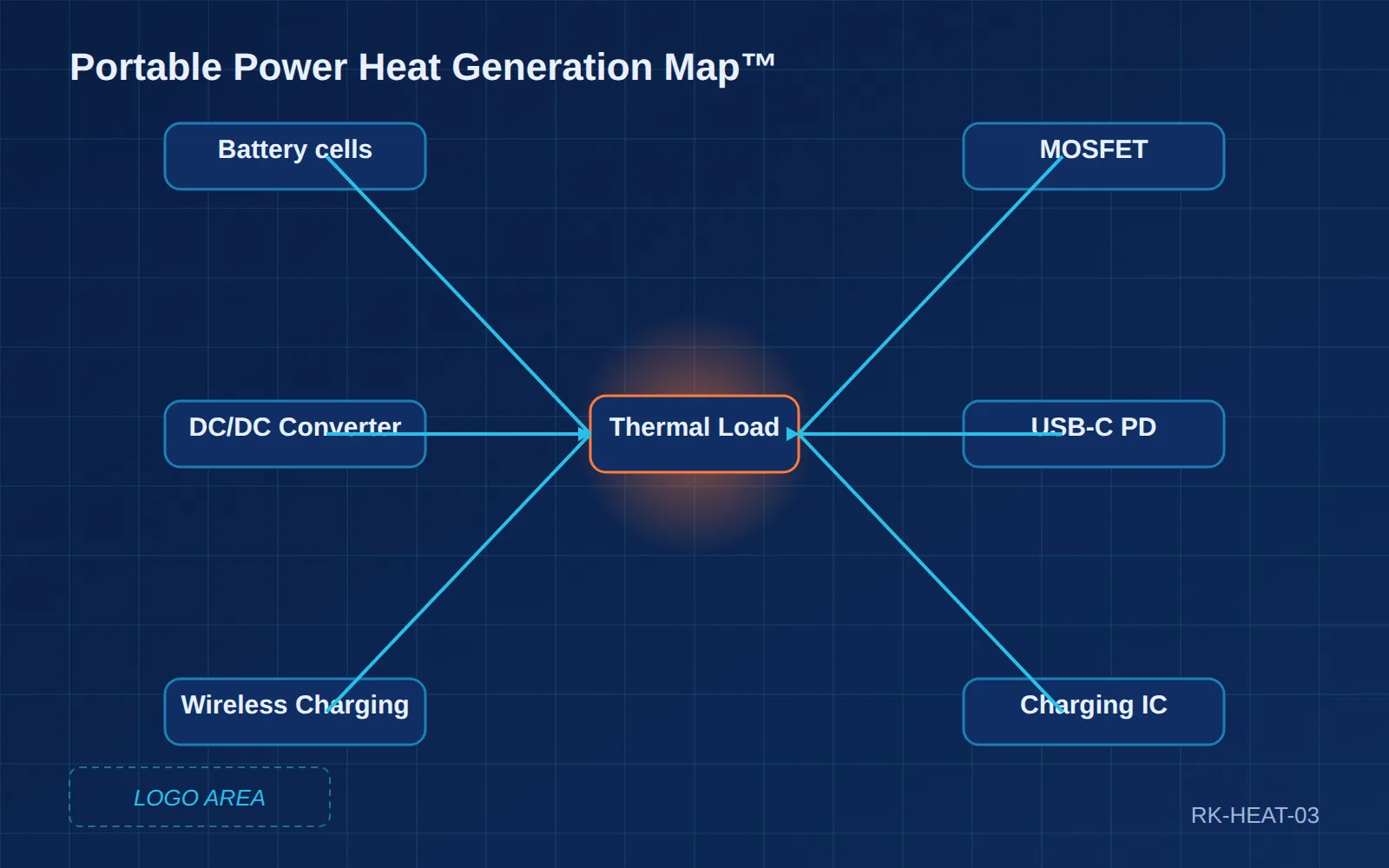
Typical heat sources include:
Battery cells
Internal resistance causes heat generation during charge and discharge.
Power conversion
Boost converters, buck converters and multi-stage power architectures generate conversion losses.
USB-C PD circuitry
High-power USB-C output can create substantial thermal load.
MOSFETs
Switching losses and conduction losses contribute to PCB heating.
Charging IC
Fast charging creates additional thermal load.
Wireless charging
Wireless power transfer can generate heat in coils, shielding, the receiver IC, transmitter circuitry and surrounding mechanical structures.
Display and MCU
These are generally smaller contributors but matter in long-duration applications.
The engineering objective is therefore not:
Make the battery heat-resistant.
It is:
Reduce heat generation + control heat propagation + remove heat + protect the system when limits are reached.
Part 4 — Thermal Management Architecture
6. A Practical Thermal Management Model
Reachinno recommends thinking about thermal management through four stages.
Stage 1 — Heat Generation
Identify where heat originates.
Battery → IC → MOSFET → Converter → Connector → Load
Stage 2 — Heat Spreading
Move heat away from concentrated hotspots. Possible methods include PCB copper, thermal pads, graphite sheets, aluminum structures, heat-spreading brackets and conductive interfaces.
Stage 3 — Heat Rejection
Move heat from the internal system to the surrounding environment. Possible mechanisms include natural convection, enclosure conduction, surface radiation and controlled airflow where appropriate.
Stage 4 — Thermal Protection
If temperature continues to rise: reduce charging current, reduce output power, disable selected functions, stop charging, disconnect battery, enter protection mode and recover automatically after temperature falls.
This produces a much more robust architecture than simply installing a temperature sensor.
Part 5 — Why the Enclosure Can Make Heat Worse
7. Rugged Does Not Automatically Mean Thermally Efficient
Outdoor products often need water resistance, dust protection, drop resistance, impact resistance, UV resistance and mechanical reinforcement.
These requirements can conflict with thermal performance.
- A fully sealed enclosure may protect the electronics from water but reduce natural airflow.
- A thick rubber shell may improve impact resistance but reduce heat transfer.
- A dark enclosure exposed to direct sunlight may absorb substantial solar energy.
Therefore:
Mechanical protection and thermal management must be designed together.
This is particularly important for IP-rated outdoor products. Our existing IP67 Rugged Power Solution provides a useful reference point for how enclosure protection becomes a system-engineering issue rather than simply a certification number.
Part 6 — Solar Exposure Is a Thermal Load
8. Why Direct Sunlight Changes the Engineering Problem
A product placed under direct sunlight is not operating under the same conditions as a product sitting in shade.
Solar radiation adds energy directly to the enclosure. This can create a situation where ambient temperature equals 40°C while product surface temperature exceeds ambient and internal battery temperature exceeds surface temperature, depending on enclosure color, material, surface finish, solar angle, exposure duration, airflow and internal heat generation.
Outdoor temperature testing without solar exposure does not fully represent a real outdoor deployment.
This is particularly important for outdoor lighting, security cameras, solar chargers, camping equipment, cycling electronics, agricultural monitoring and remote IoT equipment.
Part 7 — Solar Charging Creates a Double Thermal Challenge
9. Solar + Battery Is Not Simply “Free Energy”
Solar integration introduces an additional engineering loop:
Sunlight → Solar Panel → Solar Controller → Battery → BMS → DC/DC → Load
Solar generation itself varies with irradiance, clouds, shading, panel orientation, temperature, dust, rain, snow and time of day. NREL maintains extensive photovoltaic performance tools because irradiance and temperature are fundamental variables in PV system performance (NREL PV Data Tools).
The system therefore has two simultaneous challenges:
Energy variability
How much energy is available?
Thermal variability
How hot does the system become while collecting and storing that energy?
For outdoor portable power, solar should therefore be treated as an energy-generation subsystem, not merely a charging accessory.
Part 8 — MPPT and Power Conversion
10. Why Solar Controller Selection Matters
When solar input is integrated into a battery system, the controller determines how effectively variable PV power can be converted into useful battery energy. An MPPT controller continuously adjusts the operating point of the solar array to extract power around its maximum-power region, while also converting the voltage to match the battery/load architecture (Victron Energy).
This becomes particularly useful when solar irradiance changes, panel temperature changes, battery voltage changes, load changes or cable losses become significant.
For portable products, the exact architecture should be selected according to panel power, battery voltage, input voltage range, charging current, enclosure size, thermal budget and expected solar conditions.
There is no universal “best” solar controller.
Part 9 — BMS Is the Thermal Gatekeeper
11. What Should a BMS Do in High-Temperature Portable Power?
A BMS should not be treated simply as a protection board. In an outdoor high-temperature product, the BMS can participate in over-charge protection, over-discharge protection, over-current protection, short-circuit protection, cell balancing, temperature monitoring, charge-temperature control, discharge-temperature control, recovery logic and abnormal-condition management.
The critical point is that charging and discharging should not necessarily share the same temperature limits.
A battery may tolerate a certain discharge temperature while requiring a more restrictive charging window.
This is why BMS strategy should be defined together with the selected cell.
Part 10 — High-Temperature Charging Requires Special Attention
12. Why Charging in Heat Is More Difficult
Charging already generates heat. Now combine a hot environment, battery charging, high current and poor heat dissipation and the thermal margin can disappear quickly. Apple uses automatic thermal protections on consumer devices, including slowing or pausing charging when temperature becomes excessive (Apple Support).
For OEM products, the same engineering principle applies at a system level:
Charging power should be dynamically controlled according to actual thermal conditions.
Possible strategies include reducing charge current, limiting high-power charging, pausing charging, delaying charging until temperature falls, controlling charge SOC, prioritizing load over battery charging and using temperature sensors at critical locations.
The exact strategy depends on the application.
Part 11 — Cell Selection for Hot Environments
13. There Is No Universal “Best Battery”
When evaluating cells for extreme heat, OEM teams should compare:
| Parameter | Why It Matters |
|---|---|
| Chemistry | Determines thermal and electrochemical behavior |
| Energy density | Determines product size |
| Internal resistance | Influences heat generation |
| Cycle life | Determines long-term value |
| High-temperature performance | Determines usable operating range |
| Charging performance | Determines recharge reliability |
| Safety characteristics | Determines protection requirements |
| Supplier consistency | Determines mass-production stability |
| Cost | Determines commercial viability |
The best cell is therefore not necessarily the highest energy-density cell, or the cheapest cell. It is the cell that best matches environment, load, runtime, safety, cost and lifecycle.
This is exactly the type of application-specific battery selection discussed in the broader Reachinno battery technology research and 2026 Power Bank Industry Report.
Part 12 — High Temperature and Different Battery Chemistries
14. Lithium-Ion, LFP and Emerging Chemistries
Different battery technologies have different trade-offs.
Conventional lithium-ion
Advantages: high energy density, mature supply chain, compact form factor, broad manufacturing ecosystem.
Potential challenges: thermal sensitivity, aging at elevated temperature, safety requirements.
LFP
Advantages may include strong thermal stability, long cycle life and robust safety characteristics.
Trade-offs include lower energy density than some conventional lithium-ion chemistries, different voltage characteristics and different system architecture requirements.
Semi-solid-state
Potential advantages include improved safety architecture, potentially improved energy density and emerging application opportunities.
But OEM teams should distinguish technology potential from verified production performance.
A battery technology should be selected based on validated requirements rather than marketing claims.
Part 13 — Thermal Simulation Before Tooling
15. Why Thermal Design Should Start Before the Mold
A common product-development mistake is: design beautiful enclosure, finalize PCB, build prototype, discover heat problem, modify structure, modify PCB, modify tooling. This creates unnecessary cost.
Thermal management should begin during ID → ME → EE → Battery → PCBA coordination.
At the concept stage, engineers should identify expected ambient temperature, expected battery temperature, peak output power, average output power, charging power, solar input, converter efficiency, enclosure material, heat-spreading path and temperature sensor locations.
The goal is to avoid discovering a thermal problem after tooling begins.
Part 14 — Outdoor Product Testing
16. What Should Be Tested?
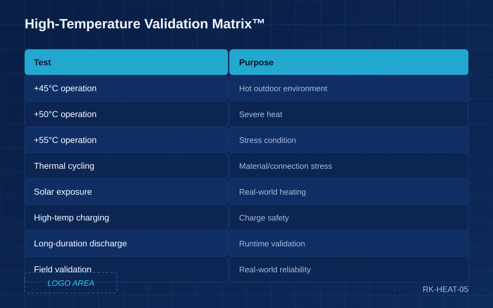
A high-temperature outdoor portable power product should be tested under more than one temperature condition. A practical validation matrix may include:
| Test | Purpose |
|---|---|
| Room-temperature baseline | Establish reference |
| +45°C operation | Hot outdoor environment |
| +50°C operation | Severe heat |
| +55°C operation | Stress condition where applicable |
| High-temperature charging | Verify charge safety |
| High-temperature discharge | Verify output stability |
| Thermal cycling | Evaluate material and connection stress |
| Solar exposure | Evaluate real-world heating |
| Humidity | Evaluate moisture interaction |
| Water ingress | Validate enclosure |
| Drop | Mechanical reliability |
| Vibration | Transportation / outdoor use |
| Long-duration discharge | Runtime validation |
| Recovery test | Verify thermal protection |
The exact temperatures should be defined according to the target product and applicable standards.
Part 15 — Laboratory Testing vs Real Outdoor Testing
17. Why Laboratory Testing Is Not Enough
A laboratory provides controlled temperature, controlled humidity, controlled current, controlled voltage and controlled load.
Real outdoor environments add direct sunlight, wind, dust, irregular load, rain, condensation, physical movement, changing solar angle and human operation.
Laboratory validation controls variables. Field validation exposes interactions between variables.
For products intended for long-term outdoor deployment, both are valuable. This principle is also consistent with the engineering approach documented in Reachinno’s -40°C outdoor case study, where controlled testing and real-world outdoor validation were treated as complementary rather than interchangeable.
Part 16 — Extreme Heat Product Architecture
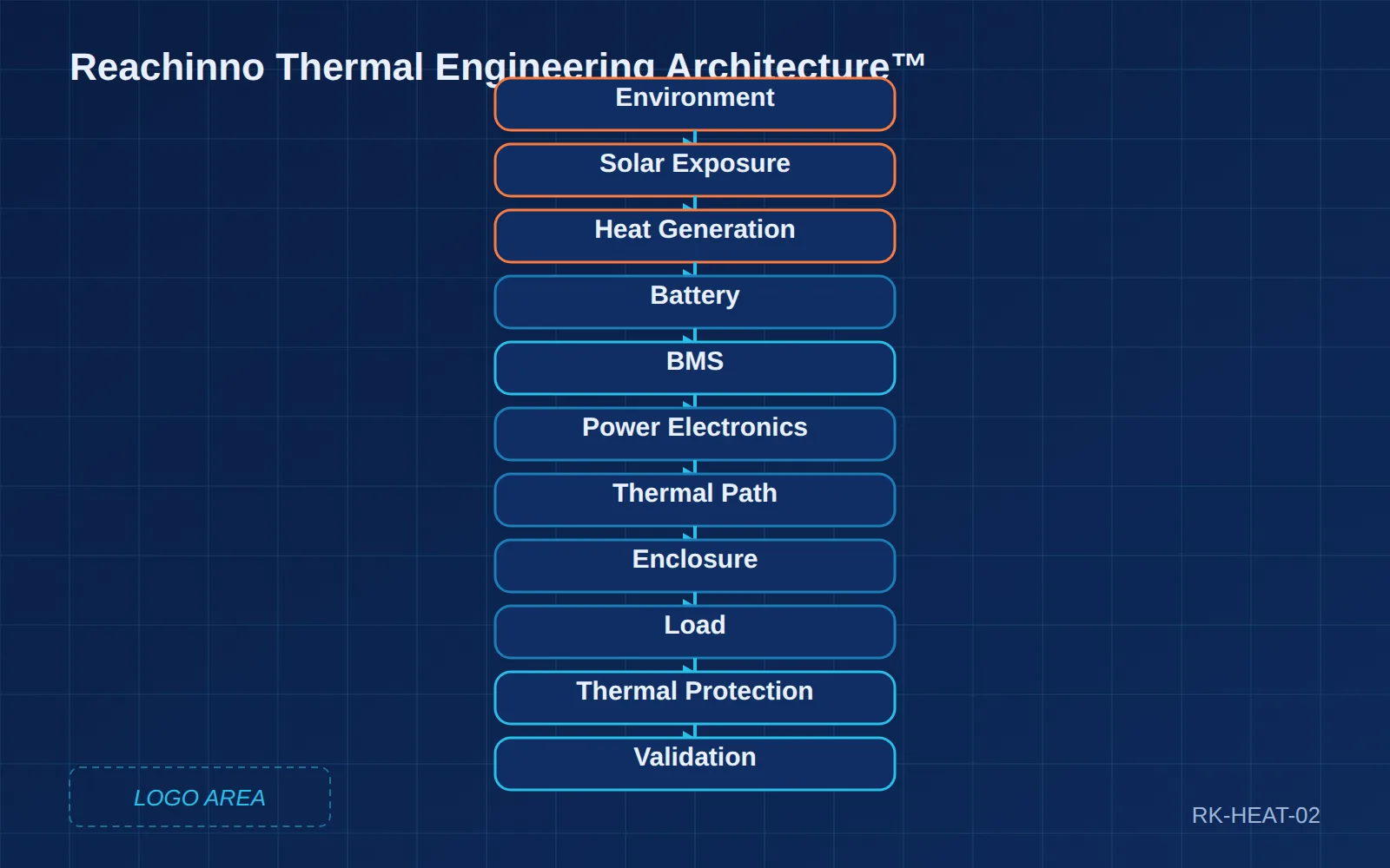
18. Reachinno Thermal Engineering Architecture™
A practical high-temperature portable power architecture can be represented as:
Environment → Solar + Ambient Heat → Battery Cell → Battery Pack → Temperature Sensors → BMS → Power Conversion → Thermal Path → Enclosure → Load → Thermal Protection → Validation
The important point is that thermal engineering crosses the entire system.
A battery engineer cannot solve it alone. A mechanical engineer cannot solve it alone. A firmware engineer cannot solve it alone. The system must be designed collaboratively.
Part 17 — Application-Specific Thermal Engineering
19. Different Applications Need Different Solutions
Camping
Priorities: portability, moderate output, weather resistance, acceptable heat dissipation. For consumer-side camping power selection, see our How to Choose a Power Bank for Camping in 2026 guide.
Cycling
Priorities: weight, vibration, direct sunlight, compact thermal design.
Outdoor Lighting
Priorities: long runtime, low standby consumption, high environmental reliability, solar compatibility.
Security Camera
Priorities: continuous operation, low standby current, thermal stability, weather protection.
Industrial IoT
Priorities: long lifecycle, temperature range, remote monitoring, low maintenance.
Emergency Power
Priorities: availability, storage stability, rapid deployment, environmental resilience.
This demonstrates why there is no universal outdoor power architecture.
Part 18 — What OEM Buyers Should Specify
20. Do Not Specify Only “50°C”
A weak RFQ might say:
Need a 20,000mAh power bank that works at 50°C.
That specification is incomplete. A stronger RFQ should specify:
Environment
Ambient temperature, direct sunlight, humidity, dust, rain, altitude.
Load
Output voltage, peak power, average power, standby power, duty cycle.
Charging
Input power, charging method, charging temperature, solar input.
Runtime
Required operating hours, required days, expected load profile.
Reliability
Cycle life, environmental cycles, expected product lifetime.
Protection
IP requirement, drop requirement, vibration requirement.
This system-level approach follows the principles defined in the Reachinno Outdoor Energy Ecosystem™.
Part 19 — Outdoor Heat Decision Matrix
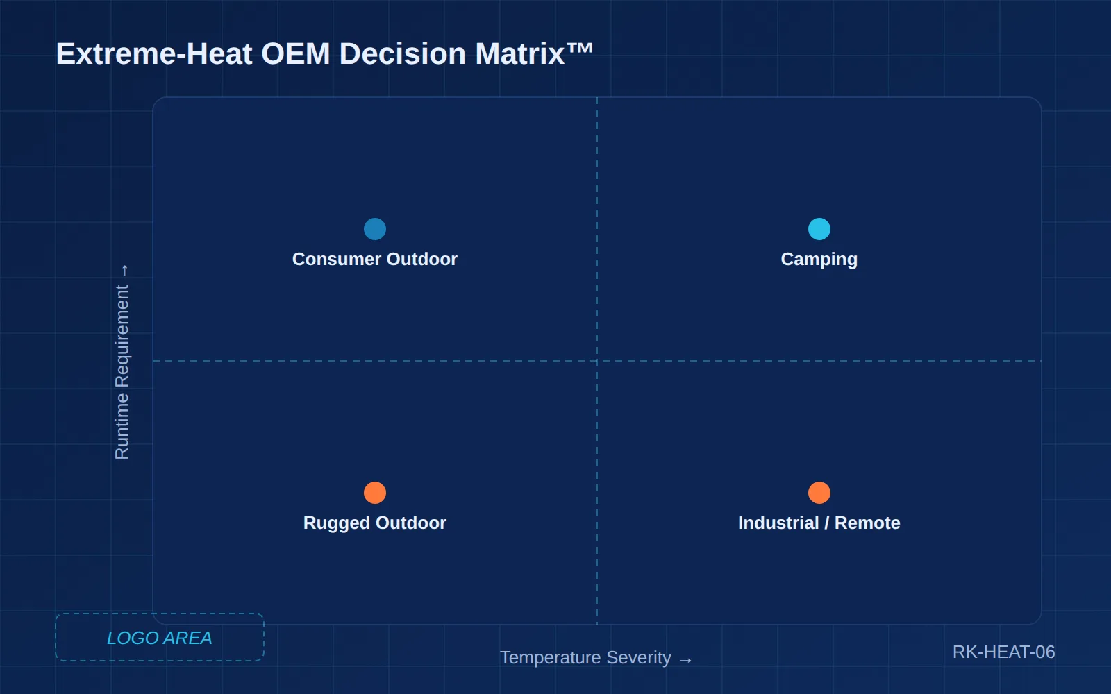
21. Practical OEM Decision Matrix
| Application | Heat Risk | Solar Exposure | Runtime | Thermal Priority |
|---|---|---|---|---|
| Hiking | Medium | Medium | 1–2 days | Weight |
| Camping | Medium | High | 1–3 days | Balance |
| Cycling | High | High | 1–3 days | Heat + weight |
| Outdoor lighting | High | High | 7–30 days | Efficiency |
| Security camera | High | High | Weeks | Reliability |
| Industrial IoT | Application-specific | Medium/High | Months | Thermal stability |
| Emergency equipment | Variable | Variable | Multi-day | Resilience |
| Solar monitoring | High | High | Weeks / months | Energy + thermal |
| Agriculture | High | High | Weeks / months | Reliability |
| Disaster response | High | Variable | Multi-day | System resilience |
Part 20 — The Five Most Common Design Mistakes
22. Mistake #1: Testing Only at Room Temperature
A product can pass every room-temperature test and still fail in the field.
23. Mistake #2: Treating Ambient Temperature as Battery Temperature
The battery may be considerably hotter than ambient because of solar exposure and internal heat generation.
24. Mistake #3: Increasing Capacity Instead of Improving Efficiency
More battery cells mean more weight, more volume, more cost and potentially more heat. For long-duration systems, reducing standby and conversion losses can sometimes provide more value. This principle is also demonstrated in Reachinno’s -40°C outdoor power case study.
25. Mistake #4: Treating IP Rating as Complete Outdoor Reliability
IP protection addresses specific ingress conditions. It does not automatically solve thermal cycling, condensation, UV exposure, mechanical impact, connector aging or internal heat accumulation.
26. Mistake #5: Selecting the Battery Before Defining the Application
The correct order should be:
Application → Environment → Load → Runtime → Battery → BMS → Electronics → Mechanical → Validation
Not Battery → Capacity → Enclosure → Product.
This is one of the core principles behind Reachinno’s Outdoor Energy Ecosystem™.
Part 21 — Future of High-Temperature Portable Power
27. Where Is the Technology Going?
Future outdoor portable power systems are likely to combine advanced lithium-ion cells, LFP, semi-solid-state batteries, smarter BMS, temperature-aware charging, high-efficiency DC/DC conversion, solar input, low standby consumption, connected monitoring, predictive maintenance, improved thermal materials and rugged mechanical architecture.
The product is gradually evolving from Battery + USB into Energy Storage + Power Management + Environmental Intelligence + Renewable Input + Application Control.
This transition is part of the larger transformation documented in Reachinno’s 2026 Power Bank Industry Report.
Part 22 — Reachinno Engineering Principle™
Extreme-heat portable power is not created by selecting a “high-temperature battery.”
Reliable performance requires coordinated optimization of:
Cell → Pack → BMS → Power Electronics → Thermal Management → Enclosure → Load → Validation
And the design must consider:
Ambient Temperature + Solar Exposure + Internal Heat + Charging + Discharging + Runtime
That is the difference between a product that merely works in a laboratory and one designed to survive real outdoor deployment.
28. Extreme Heat Is a System-Engineering Problem
The key lesson is simple: extreme-heat portable power is not created by selecting a “high-temperature battery.” Reliable performance requires coordinated optimization of cell, pack, BMS, power electronics, thermal management, enclosure, load and validation.
And the design must consider ambient temperature, solar exposure, internal heat, charging, discharging and runtime. That is the difference between a product that merely works in a laboratory and one designed to survive real outdoor deployment.
Conclusion
Extreme heat is becoming an increasingly important engineering requirement for portable power.
As portable energy moves into camping, cycling, emergency response, outdoor lighting, remote monitoring, agriculture and industrial applications, products are exposed to environmental conditions far beyond the traditional consumer-electronics operating envelope.
High temperature affects battery aging, charging behavior, power conversion, electronics reliability, enclosure performance, long-term runtime and safety margins.
The solution is not simply a larger battery or a thicker enclosure. It is system-level engineering.
Specify the environment first. Design the energy system second.
For OEM buyers, the most useful starting information is operating temperature, solar exposure, load, runtime, charging method and environmental protection. From there, the battery, BMS, electronics, thermal architecture and validation plan can be engineered around the actual application.
Reachinno approaches outdoor portable power as a product-development problem, not simply a component-sourcing problem — from battery and BMS selection to power electronics, mechanical protection, environmental validation and mass production. Explore Reachinno’s Outdoor Power Solutions for OEM and ODM development.
Related Engineering Resources
Continue the outdoor portable power engineering journey with these companion resources from the Reachinno knowledge map.
Research
2026 Power Bank Industry Report — Understand how AI devices, battery technology, compliance and supply chain are reshaping the portable power industry.
Framework
Reachinno Outdoor Energy Ecosystem™ — Environment → Load → Battery → Electronics → Protection → Validation. The complete engineering system behind every Reachinno outdoor product.
Technical Guide
Extreme-Weather Portable Power in 2026 — The cornerstone engineering guide covering cold, heat, water, solar and emergency portable power scenarios.
Case Study
Engineering Portable Power for -40°C — 7,500mAh, 22-day outdoor lighting application, -40°C engineering validation.
Buyer Guide
How to Choose a Power Bank for Camping in 2026 — Capacity, output, runtime, temperature, solar and outdoor use selection criteria.
Browse more on the Reachinno blog.
Read by: Reachinno Engineering Team.
FAQ
What temperature is too hot for a lithium-ion power bank?
There is no single universal temperature limit for every lithium-ion cell or product. The allowable temperature depends on cell design, chemistry, charging/discharging conditions and system architecture. Product teams should always use the cell manufacturer’s verified specifications and validate the complete product under its intended environmental conditions.
Does hot weather permanently damage lithium-ion batteries?
Prolonged exposure to elevated temperature can accelerate battery degradation and reduce long-term capacity and lifespan. The effect depends on temperature, time, state of charge, charge/discharge rate and chemistry. The U.S. Department of Energy identifies temperature as an important factor in lithium-ion degradation.
Can a power bank charge in 50°C weather?
It depends on the specific battery and charging system. Charging at elevated temperatures can require reduced current, thermal protection or charging suspension. OEM products should be validated against the intended charging temperature rather than assuming that a discharge rating also applies to charging.
Does solar charging make a power bank hotter?
It can. Solar charging introduces additional energy into the system, while the solar-exposed enclosure can also absorb heat. The combined effect of solar radiation, charging losses and ambient temperature should therefore be included in thermal validation.
Is a waterproof power bank harder to cool?
Potentially. A sealed enclosure can reduce natural airflow and alter the path through which heat leaves the system. Waterproofing and thermal management should therefore be designed together rather than sequentially.
Is LFP better for extreme heat?
LFP can offer favorable thermal and safety characteristics, but “better” depends on the complete application. Energy density, weight, voltage architecture, cycle life, cost and supplier availability also matter.
What should OEM buyers ask about a high-temperature battery?
Ask for verified operating-temperature range, verified charging-temperature range, usable capacity at temperature, internal resistance, cycle-life data, thermal protection strategy, BMS temperature limits, validation data, cell consistency and supplier traceability.
Can a standard power bank be modified for extreme heat?
Usually not by simply changing the enclosure. High-temperature performance can require coordinated changes to the cell, BMS, power electronics, thermal path, mechanical structure and firmware.
How should an outdoor power product be tested for heat?
Testing should combine controlled high-temperature operation, high-temperature charging/discharging, thermal cycling, solar exposure where relevant, long-duration operation and real-world field validation.
Why is solar exposure important in outdoor battery testing?
Because ambient temperature alone does not capture the thermal load created by direct solar radiation. The actual product surface and internal component temperatures can differ substantially from ambient conditions.
What information should I provide when requesting an extreme-heat portable power solution?
Provide: (1) minimum and maximum ambient temperature, (2) direct-sun exposure, (3) load voltage and power, (4) peak and average load, (5) required runtime, (6) charging method, (7) solar requirements, (8) IP requirement, (9) product size and weight target, (10) target market and certification requirements.